The idea of the Synth Clarinet is pretty straightforward – this is a synthesizer with an interface set up in a similar fashion to a wind instrument. There are 8 note controlling buttons, and a microphone to sense breath input and control volume, just like a mouthpiece.
Time to explain this whole thing from top to bottom!
The first thing we need in any synth is a note to output. So, the whole thing begins with an oscillator. Here’s what it looks like: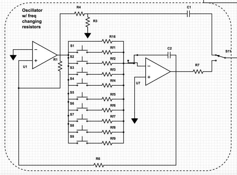
The point of an oscillator is to generate some kind of sound wave or signal. This particular oscillator has two outputs, giving both a square wave from the top and a triangle wave from the bottom part. The switch, S11, at the end, allows the user to choose which wave they want to hear. The two wave generators rely on each other to function.
Now, you may see this little thing in the middle of it all, and say, “what the damned hell is that?” Well, never fear, this is actually super duper simple.

The equation for frequency in an oscillator is
f = (1/(4Rt*C))*(R2/R1)
The resistance between the output of the first op amp and the inverting input of the second is Rt, while R2 and R1 are referred to as R1 and R6 in my schematic, and C is the capacitor in the 2nd op amp’s feedback loop, C2. This section of the oscillator is the interface portion found on the second breadboard. Every line across has a resistor symbol, the jagged line, and before each of them is the symbol for a button. Whenever one of these buttons is pressed down, the signal flows through that resistor in parallel with whatever else is pressed down, as well as the one open resistor at the top, which gives the open note. When actually put on the breadboard, each of these resistors is put in series with a trimpot, which allows the user to tune notes.
Voila, we have notes! Now, we have to get the mouthpiece to control those notes. The idea here is that we are going to use an LED/photoresistor combo. An LED, or Light Emitting Diode, is essentially just a light controlled by voltage, and a Photoresistor is just a resistor that changes how much resistance it is giving a signal depending on how much light it is exposed to at any given time. The microphone controls the LED brightness, and the photoresistor then reacts to that by changing its resistance. The photoresistor will be part of an amplifier circuit, and therefore the amplification of the sound will change based on the brightness of the LED.
Now, how do we make this happen? The first thing we need is to get the microphone itself to work.

The mic used in this project is a small electret microphone, which acts kind of like a variable resistor. So, it needs a little power to run through it, so we put a 10kΩ resistor from power to one side, and the other to ground, with an output on the powered side to the rest of the circuit. The mic acts kind of like a voltage divider here, so when you blow in, less voltage can pass through the mic, and then more power travels through the circuit. The 1µF resistor is there as a Hi-pass filter to knock off any DC voltage.
After that, the problem is, the signal from the mic is so tiny that it’s nothing. So, we need to amplify it!

This inverting amplifier uses an op amp feedback loop to make the signal louder, but the resistor limits the feedback amount and therefore makes it not light on fire. The gain, or amount amplified, is determined by the ratio of the two resistors. The equation is
A = 1 + R2/R1
where R2 is the 100kΩ and R1 is the 1kΩ. So, this amplifier gives a gain of 100 to the microphone signal, which is great.
Now, we have this loud signal which is wonderful, but it is super jumpy. So, we need something to smoothen it out, so that we get a constant tone from blowing into the mic, and so that the attack and decay are smooth. An envelope follower does exactly that.

An envelope follower makes the signal smooth. The above circuit shows exactly how the circuit is built. The circuit relies on the one way conduction of diodes. The one thing that is interesting to mess with in this piece of the circuit is the capacitor, C4. The value of this cap controls the attack/decay time of the follower. I currently have it at 200µF, which gives a really nice decay. The less capacitance there, the smaller the attack and decay get, to the point where it’s really jumpy if its really small. The more capacitance you put there, the longer the attack and decay get. It’s a really cool thing.
Now, we have a pretty sweet signal we can send to an LED.

The best way to do this is in the above schematic, where you put a resistor before, and put a diode conducting from the negative input into the output. Backwards from a feedback loop.
The LED and the photoresistor need to be taped together well, in a way that will let no/very little light in or out. I personally taped mine together with masking tape, and covered the combo with a black velcro cable tie, which worked absolutely perfectly. Sounds a bit janky, but whatever works, you know?
Now, back to the oscillator for the final step! Now we use the photoresistor to control a non-inverting amplifier. I had R14 at 20Ω, which seems tiny, but it got the signal to go to zero when the LED was completely dark, at which point it was at about 4kΩ.

Here is the amplifier circuit where the photoresistor controls the output volume. Then, there’s the output safety, which is just a capacitor and a 100Ω resistor.
That’s all there is to it! Below is the schematic to the entire thing.
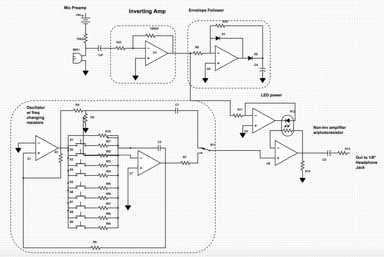

6 thoughts on “Final Project: Synth Clarinet”